Laser ablation as a process has
many advantages over mechanical machining, certainly in the
area of micromachining and engraving.
Apart from being a non-contact technique, it allows a wide
range of materials to be machined and very small dimensions
and high resolution and accuracy to be achieved. Open tool
paths are easily achieved by simply switching the laser off
while moving to the starting point of the next tool path rather
than lifting the tool out of the workpiece. And it is not
necessary to drill pilot holes in order to move the tool into
position in the first place.
Also there is no tool radius, so corners can be infinitely
sharp.
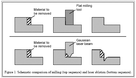
On the other hand, laser ablation is a much more complex process
than for example milling. Figure 1 illustrates in a schematic
and simplified way the differences between milling and laser
ablation.
Figure 1: Schematic comparison of milling (top sequence) and
laser ablation (bottom sequence).

Whereas with milling, the result
of a machining operation is completely determined by the geometry
and the position of the tool, this is not so with laser ablation.
One fundamental issue is the depth control: Given the length
of a milling tool you can easily position it so that it will
remove material exactly down to a predefined absolute z-level.
A laser beam, however, machines down to a certain depth relative
to the surface – wherever the surface is. In particular,
overlap of tool paths results in extra depth.
Similarly, with milling the profile of the cut is entirely
determined by the shape of the milling tool. With laser ablation,
on the other hand, there are many factors that influence the
profile of the cut: The beam profile and shape, laser parameters
such as the pulse repetition rate and the shot overlap, physical
properties of the material (e.g. optical penetration depth,
thermal diffusivity), the curvature of the tool path (the
cut will be deeper at the inside of a curve due to higher
shot overlap) and the shape of the surface of the substrate.
Thankfully this is not a problem when laser ablation is used
for engraving trophies, plaques, lables and the like.
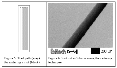
In many cases,
the most efficient way to
machine a slot is not cutting along its
edges, but raster scanning the whole slot.
This technique is the analogue to the
spiraling technique for hole drilling and
has the same effect: Material is removed
from the whole area of the slot in order
to avoid a narrow cut. Again, it is not the
technique itself that is innovative, but the
ease of use and convenience provided by our software.
As an example of an application for slot
cutting we can mention the machining of
ink feeding slots for ink jet printer heads. |
 |
|
2D area clearing is mainly used for
single shot processes where no depth control is required,
e.g. for patterning of layers on glass, metals or flexible
substrates as required for flat panel displays.
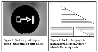
Tool paths are generated that allow all the material
in the areas defined by the
borderlines in the CAD drawing to be
removed. In the case of nested borderlines, we build
up a tree structure reflecting which borderline is inside
which. This allows us to identify the different regions,
each of which is delimited by an outer border and possibly
contains islands. The rastering prossess is shown in
Figure 8.
|
 |
For more information
on laser engraving  For more information on image resolution/DPI
|
ACKNOWLEDGEMENTS : Information
in this article are extracts from a paper "CAD/CAM software
for an industrial laser manufacturing" written by Exitech
Ltd, Oxford Industrial Park, Yarnton, Oxford, UK; and Imperial
College of Science, Technology and Medicine, Dept. of Electrical
and Electronic Engineering, London, UK.